Sketch Driven Sheet Metal Part

Autodesk Inventor Sheet Metal Tutorial Basics Youtube Autodesk Inventor Metal Furniture Design Solidworks Tutorial

Pin On Solidworks

Solidworks Tutorial Sketch Sheet Metal Screw In Solidworks Youtube

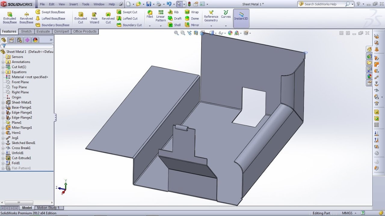
Solidworks Sheet Metal Tutorial Switch Box Youtube Sheet Metal Drawing Solidworks Tutorial Sheet Metal

Solidworks Sheet Metal Lofted Bend Youtube Sheet Metal Drawing Solidworks Sheet Metal

Solidworks Sheet Metal Tutorial Hopper Youtube In 2020 Sheet Metal Sheet Metal Drawing Metal Sheet Design

Thickness to diameter ratio is a main factor used to quantify the geometry of a blank and can be calculated by t d b.
Sketch driven sheet metal part.

Autodesk Inventor Sheet Metal Stairway Configurator Autodesk Inventor Inventor Stairways

Autodesk Inventor Driven Dimensions And Template Sketches Autodesk Inventor Inventor Sketches

Solidworks Sheet Metal Exercise Youtube Sheet Metal Drawing Sheet Metal Solidworks

Solidworks Tutorial Design And Assembly Of Car Jack In Solidworks So Solidworks Tutorial Car Jack Solidworks

558 Sw Final Exam Sheet Metal Youtube Solidworks Tutorial Solidworks Final Exams

Pin On Sketch

Solidworks Tutorial Sketch Kitchen Sink In Solidworks Solidworks Solidworks Tutorial Mechanical Engineering Design

Take A Tour Of The New Bikecad Ca Website And Learn About Bikecad And Bikecad Pro Bikecad And Bikecad Pro Req Solidworks Tutorial Solidworks Mechanical Design

Undefined In 2020 Solidworks Tutorial Solidworks Sketch Design

Autodesk Inventor Sketch Basics Part 5 Driven Dimensions Autodesk Inventor Autocad Inventor Autodesk

Slide 1888 Jpg 639 509 Steel Sheet Metal Steel Deck Steel Beams

Curve Driven Pattern Tip Solidworks Tutorial Solidworks Tutorial

Solidworks Curve Driven Pattern Feature With Images Solidworks Pattern Curve

Solidworks Tutorial Design And Assembly Of Ball Bearing In Solidworks Solidworks Solidworks Tutorial Solidworks Mechanical Engineering

Simple System Sloped Sheet Metal Coping Sketch Drawing The Image Shows A Sketch Of Metal Coping Installed Over Parapet Wall Parapet Sheet Metal Roof Design
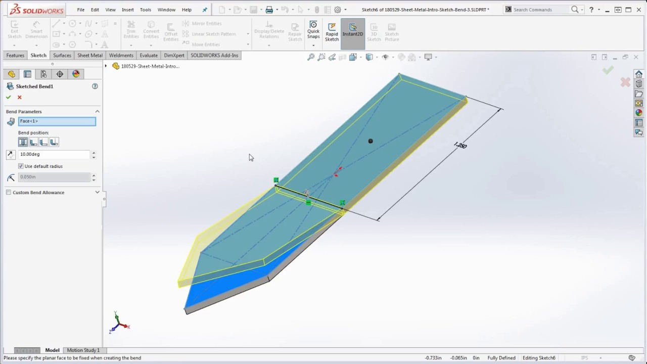
23 Solidworks How To Bend A Part Using The Sketch Bend Feature Intro To Solidworks Sheet Metal Youtube
Solidworks Convert To Sheet Metal Cylinder Youtube
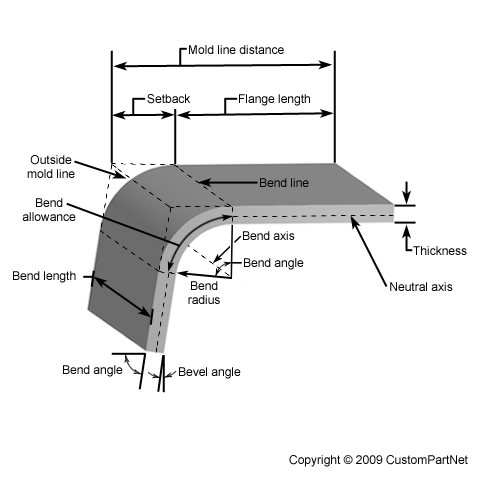
Sheet Metal Forming
Https Encrypted Tbn0 Gstatic Com Images Q Tbn 3aand9gcsftkzqgtggsbgs5vksvlmj5nx5ovb560qcfwk2uwxdpjil9xvk Usqp Cau

Explore Gbarnes S Photos On Photobucket Sheet Metal Metal Bender Sheet Metal Brake

Solidworks Tutorial Sketch Bearing Puller In Solidworks Youtube In 2020 Solidworks Tutorial Solidworks Mechanical Engineering Design

Schroeder Art Metal Shaping Metal Fabrication Electric Car

Pin On Fiber Laser Cutting Machine

Pin On Mechanical Engineering
Source : pinterest.com
